.jpg) Pn Habshah is having Chemistry class with the PPUAA but only three students turned up.
Pn Habshah is having Chemistry class with the PPUAA but only three students turned up..jpg)
Thursday, March 25, 2010
Thursday, March 18, 2010
ATOMIC ORBITAL
ATOMIC ORBITALS
What is an atomic orbital?
Orbitals and orbits
When the a planet moves around the sun, you can plot a definite path for it which is called an orbit. A simple view of the atom looks similar and you may have pictured the electrons as orbiting around the nucleus. The truth is different, and electrons in fact inhabit regions of space known as orbitals.Orbits and orbitals sound similar, but they have quite different meanings. It is essential that you understand the difference between them.The impossibility of drawing orbits for electrons
To plot a path for something you need to know exactly where the object is and be able to work out exactly where it's going to be an instant later. You can't do this for electrons.
The Heisenberg Uncertainty Principle says - loosely - that you can't know with certainty both where an electron is and where it's going next. (What it actually says is that it is impossible to define with absolute precision, at the same time, both the position and the momentum of an electron.)
That makes it impossible to plot an orbit for an electron around a nucleus. Is this a big problem? No. If something is impossible, you have to accept it and find a way around it.
Note: Over the years I have had a steady drip of questions from students in which it is obvious that they still think of electrons as orbiting around a nucleus - which is completely wrong! I have added a page about why the idea of orbits is wrong to try to avoid having to say the same thing over and over again!
Hydrogen's electron - the 1s orbital
 Note: In this diagram (and the orbital diagrams that follow), the nucleus is shown very much larger than it really is. This is just for clarity.
Suppose you had a single hydrogen atom and at a particular instant plotted the position of the one electron. Soon afterwards, you do the same thing, and find that it is in a new position. You have no idea how it got from the first place to the second.
You keep on doing this over and over again, and gradually build up a sort of 3D map of the places that the electron is likely to be found.
In the hydrogen case, the electron can be found anywhere within a spherical space surrounding the nucleus. The diagram shows a cross-section through this spherical space.
95% of the time (or any other percentage you choose), the electron will be found within a fairly easily defined region of space quite close to the nucleus. Such a region of space is called an orbital. You can think of an orbital as being the region of space in which the electron lives.
Note: If you wanted to be absolutely 100% sure of where the electron is, you would have to draw an orbital the size of the Universe!
What is the electron doing in the orbital? We don't know, we can't know, and so we just ignore the problem! All you can say is that if an electron is in a particular orbital it will have a particular definable energy.
Each orbital has a name.
The orbital occupied by the hydrogen electron is called a 1s orbital. The "1" represents the fact that the orbital is in the energy level closest to the nucleus. The "s" tells you about the shape of the orbital. s orbitals are spherically symmetric around the nucleus - in each case, like a hollow ball made of rather chunky material with the nucleus at its centre.
The orbital on the left is a 2s orbital. This is similar to a 1s orbital except that the region where there is the greatest chance of finding the electron is further from the nucleus - this is an orbital at the second energy level.
If you look carefully, you will notice that there is another region of slightly higher electron density (where the dots are thicker) nearer the nucleus. ("Electron density" is another way of talking about how likely you are to find an electron at a particular place.)
2s (and 3s, 4s, etc) electrons spend some of their time closer to the nucleus than you might expect. The effect of this is to slightly reduce the energy of electrons in s orbitals. The nearer the nucleus the electrons get, the lower their energy.
3s, 4s (etc) orbitals get progressively further from the nucleus.
p orbitals
Not all electrons inhabit s orbitals (in fact, very few electrons live in s orbitals). At the first energy level, the only orbital available to electrons is the 1s orbital, but at the second level, as well as a 2s orbital, there are also orbitals called 2p orbitals.
 A p orbital is rather like 2 identical balloons tied together at the nucleus. The diagram on the right is a cross-section through that 3-dimensional region of space. Once again, the orbital shows where there is a 95% chance of finding a particular electron.
Taking chemistry further: If you imagine a horizontal plane through the nucleus, with one lobe of the orbital above the plane and the other beneath it, there is a zero probability of finding the electron on that plane. So how does the electron get from one lobe to the other if it can never pass through the plane of the nucleus? At this introductory level you just have to accept that it does! If you want to find out more, read about the wave nature of electrons.
Unlike an s orbital, a p orbital points in a particular direction - the one drawn points up and down the page.
At any one energy level it is possible to have three absolutely equivalent p orbitals pointing mutually at right angles to each other. These are arbitrarily given the symbols px, py and pz. This is simply for convenience - what you might think of as the x, y or z direction changes constantly as the atom tumbles in space.
The p orbitals at the second energy level are called 2px, 2py and 2pz. There are similar orbitals at subsequent levels - 3px, 3py, 3pz, 4px, 4py, 4pz and so on.
All levels except for the first level have p orbitals. At the higher levels the lobes get more elongated, with the most likely place to find the electron more distant from the nucleus.
d and f orbitals
In addition to s and p orbitals, there are two other sets of orbitals which become available for electrons to inhabit at higher energy levels. At the third level, there is a set of five d orbitals (with complicated shapes and names) as well as the 3s and 3p orbitals (3px, 3py, 3pz). At the third level there are a total of nine orbitals altogether.
At the fourth level, as well the 4s and 4p and 4d orbitals there are an additional seven f orbitals - 16 orbitals in all. s, p, d and f orbitals are then available at all higher energy levels as well.
For the moment, you need to be aware that there are sets of five d orbitals at levels from the third level upwards, but you probably won't be expected to draw them or name them. Apart from a passing reference, you won't come across f orbitals at all.
Note: Some UK-based syllabuses will eventually want you to be able to draw, or at least recognise, the shapes of d orbitals. I am not including them now because I don't want to add confusion to what is already a difficult introductory topic. Check your syllabus and past papers to find out what you need to know. If you are a studying a UK-based syllabus and haven't got these, follow this link to find out how to get hold of them.
Fitting electrons into orbitals
You can think of an atom as a very bizarre house (like an inverted pyramid!) - with the nucleus living on the ground floor, and then various rooms (orbitals) on the higher floors occupied by the electrons. On the first floor there is only 1 room (the 1s orbital); on the second floor there are 4 rooms (the 2s, 2px, 2py and 2pz orbitals); on the third floor there are 9 rooms (one 3s orbital, three 3p orbitals and five 3d orbitals); and so on. But the rooms aren't very big . . . Each orbital can only hold 2 electrons.
A convenient way of showing the orbitals that the electrons live in is to draw "electrons-in-boxes".
"Electrons-in-boxes"
Orbitals can be represented as boxes with the electrons in them shown as arrows. Often an up-arrow and a down-arrow are used to show that the electrons are in some way different.
Taking chemistry further: The need to have all electrons in an atom different comes out of quantum theory. If they live in different orbitals, that's fine - but if they are both in the same orbital there has to be some subtle distinction between them. Quantum theory allocates them a property known as "spin" - which is what the arrows are intended to suggest.
A 1s orbital holding 2 electrons would be drawn as shown on the right, but it can be written even more quickly as 1s2. This is read as "one s two" - not as "one s squared".
You mustn't confuse the two numbers in this notation:
The order of filling orbitals
Electrons fill low energy orbitals (closer to the nucleus) before they fill higher energy ones. Where there is a choice between orbitals of equal energy, they fill the orbitals singly as far as possible.
This filling of orbitals singly where possible is known as Hund's rule. It only applies where the orbitals have exactly the same energies (as with p orbitals, for example), and helps to minimise the repulsions between electrons and so makes the atom more stable.
The diagram (not to scale) summarises the energies of the orbitals up to the 4p level.
Notice that the s orbital always has a slightly lower energy than the p orbitals at the same energy level, so the s orbital always fills with electrons before the corresponding p orbitals.
The real oddity is the position of the 3d orbitals. They are at a slightly higher level than the 4s - and so it is the 4s orbital which will fill first, followed by all the 3d orbitals and then the 4p orbitals. Similar confusion occurs at higher levels, with so much overlap between the energy levels that the 4f orbitals don't fill until after the 6s, for example.
For UK-based exam purposes, you simply have to remember that the 4s orbital fills before the 3d orbitals. The same thing happens at the next level as well - the 5s orbital fills before the 4d orbitals. All the other complications are beyond the scope of this site.
What is an atomic orbital?
Orbitals and orbits
When the a planet moves around the sun, you can plot a definite path for it which is called an orbit. A simple view of the atom looks similar and you may have pictured the electrons as orbiting around the nucleus. The truth is different, and electrons in fact inhabit regions of space known as orbitals.Orbits and orbitals sound similar, but they have quite different meanings. It is essential that you understand the difference between them.The impossibility of drawing orbits for electrons
To plot a path for something you need to know exactly where the object is and be able to work out exactly where it's going to be an instant later. You can't do this for electrons.
The Heisenberg Uncertainty Principle says - loosely - that you can't know with certainty both where an electron is and where it's going next. (What it actually says is that it is impossible to define with absolute precision, at the same time, both the position and the momentum of an electron.)
That makes it impossible to plot an orbit for an electron around a nucleus. Is this a big problem? No. If something is impossible, you have to accept it and find a way around it.
Note: Over the years I have had a steady drip of questions from students in which it is obvious that they still think of electrons as orbiting around a nucleus - which is completely wrong! I have added a page about why the idea of orbits is wrong to try to avoid having to say the same thing over and over again!
Hydrogen's electron - the 1s orbital
 Note: In this diagram (and the orbital diagrams that follow), the nucleus is shown very much larger than it really is. This is just for clarity.
Suppose you had a single hydrogen atom and at a particular instant plotted the position of the one electron. Soon afterwards, you do the same thing, and find that it is in a new position. You have no idea how it got from the first place to the second.
You keep on doing this over and over again, and gradually build up a sort of 3D map of the places that the electron is likely to be found.
In the hydrogen case, the electron can be found anywhere within a spherical space surrounding the nucleus. The diagram shows a cross-section through this spherical space.
95% of the time (or any other percentage you choose), the electron will be found within a fairly easily defined region of space quite close to the nucleus. Such a region of space is called an orbital. You can think of an orbital as being the region of space in which the electron lives.
Note: If you wanted to be absolutely 100% sure of where the electron is, you would have to draw an orbital the size of the Universe!
What is the electron doing in the orbital? We don't know, we can't know, and so we just ignore the problem! All you can say is that if an electron is in a particular orbital it will have a particular definable energy.
Each orbital has a name.
The orbital occupied by the hydrogen electron is called a 1s orbital. The "1" represents the fact that the orbital is in the energy level closest to the nucleus. The "s" tells you about the shape of the orbital. s orbitals are spherically symmetric around the nucleus - in each case, like a hollow ball made of rather chunky material with the nucleus at its centre.
The orbital on the left is a 2s orbital. This is similar to a 1s orbital except that the region where there is the greatest chance of finding the electron is further from the nucleus - this is an orbital at the second energy level.

If you look carefully, you will notice that there is another region of slightly higher electron density (where the dots are thicker) nearer the nucleus. ("Electron density" is another way of talking about how likely you are to find an electron at a particular place.)
2s (and 3s, 4s, etc) electrons spend some of their time closer to the nucleus than you might expect. The effect of this is to slightly reduce the energy of electrons in s orbitals. The nearer the nucleus the electrons get, the lower their energy.
3s, 4s (etc) orbitals get progressively further from the nucleus.
p orbitals
Not all electrons inhabit s orbitals (in fact, very few electrons live in s orbitals). At the first energy level, the only orbital available to electrons is the 1s orbital, but at the second level, as well as a 2s orbital, there are also orbitals called 2p orbitals.
 A p orbital is rather like 2 identical balloons tied together at the nucleus. The diagram on the right is a cross-section through that 3-dimensional region of space. Once again, the orbital shows where there is a 95% chance of finding a particular electron.
Taking chemistry further: If you imagine a horizontal plane through the nucleus, with one lobe of the orbital above the plane and the other beneath it, there is a zero probability of finding the electron on that plane. So how does the electron get from one lobe to the other if it can never pass through the plane of the nucleus? At this introductory level you just have to accept that it does! If you want to find out more, read about the wave nature of electrons.
Unlike an s orbital, a p orbital points in a particular direction - the one drawn points up and down the page.
At any one energy level it is possible to have three absolutely equivalent p orbitals pointing mutually at right angles to each other. These are arbitrarily given the symbols px, py and pz. This is simply for convenience - what you might think of as the x, y or z direction changes constantly as the atom tumbles in space.
The p orbitals at the second energy level are called 2px, 2py and 2pz. There are similar orbitals at subsequent levels - 3px, 3py, 3pz, 4px, 4py, 4pz and so on.
All levels except for the first level have p orbitals. At the higher levels the lobes get more elongated, with the most likely place to find the electron more distant from the nucleus.
d and f orbitals
In addition to s and p orbitals, there are two other sets of orbitals which become available for electrons to inhabit at higher energy levels. At the third level, there is a set of five d orbitals (with complicated shapes and names) as well as the 3s and 3p orbitals (3px, 3py, 3pz). At the third level there are a total of nine orbitals altogether.
At the fourth level, as well the 4s and 4p and 4d orbitals there are an additional seven f orbitals - 16 orbitals in all. s, p, d and f orbitals are then available at all higher energy levels as well.
For the moment, you need to be aware that there are sets of five d orbitals at levels from the third level upwards, but you probably won't be expected to draw them or name them. Apart from a passing reference, you won't come across f orbitals at all.
Note: Some UK-based syllabuses will eventually want you to be able to draw, or at least recognise, the shapes of d orbitals. I am not including them now because I don't want to add confusion to what is already a difficult introductory topic. Check your syllabus and past papers to find out what you need to know. If you are a studying a UK-based syllabus and haven't got these, follow this link to find out how to get hold of them.
Fitting electrons into orbitals
You can think of an atom as a very bizarre house (like an inverted pyramid!) - with the nucleus living on the ground floor, and then various rooms (orbitals) on the higher floors occupied by the electrons. On the first floor there is only 1 room (the 1s orbital); on the second floor there are 4 rooms (the 2s, 2px, 2py and 2pz orbitals); on the third floor there are 9 rooms (one 3s orbital, three 3p orbitals and five 3d orbitals); and so on. But the rooms aren't very big . . . Each orbital can only hold 2 electrons.
A convenient way of showing the orbitals that the electrons live in is to draw "electrons-in-boxes".
"Electrons-in-boxes"
Orbitals can be represented as boxes with the electrons in them shown as arrows. Often an up-arrow and a down-arrow are used to show that the electrons are in some way different.
Taking chemistry further: The need to have all electrons in an atom different comes out of quantum theory. If they live in different orbitals, that's fine - but if they are both in the same orbital there has to be some subtle distinction between them. Quantum theory allocates them a property known as "spin" - which is what the arrows are intended to suggest.
A 1s orbital holding 2 electrons would be drawn as shown on the right, but it can be written even more quickly as 1s2. This is read as "one s two" - not as "one s squared".
You mustn't confuse the two numbers in this notation:
The order of filling orbitals
Electrons fill low energy orbitals (closer to the nucleus) before they fill higher energy ones. Where there is a choice between orbitals of equal energy, they fill the orbitals singly as far as possible.
This filling of orbitals singly where possible is known as Hund's rule. It only applies where the orbitals have exactly the same energies (as with p orbitals, for example), and helps to minimise the repulsions between electrons and so makes the atom more stable.
The diagram (not to scale) summarises the energies of the orbitals up to the 4p level.
Notice that the s orbital always has a slightly lower energy than the p orbitals at the same energy level, so the s orbital always fills with electrons before the corresponding p orbitals.
The real oddity is the position of the 3d orbitals. They are at a slightly higher level than the 4s - and so it is the 4s orbital which will fill first, followed by all the 3d orbitals and then the 4p orbitals. Similar confusion occurs at higher levels, with so much overlap between the energy levels that the 4f orbitals don't fill until after the 6s, for example.
For UK-based exam purposes, you simply have to remember that the 4s orbital fills before the 3d orbitals. The same thing happens at the next level as well - the 5s orbital fills before the 4d orbitals. All the other complications are beyond the scope of this site.
Wednesday, March 17, 2010

.jpg)
.jpg)
.jpg)
Tuesday, January 26, 2010
THE MELTING POINT OF NAPHTHLENE


 The Form 4A students are trying to determine the melting point of naphthalene.
Thursday, December 10, 2009
TITRATION


 The Form 4A students are doing their titration experiment between Natrium hydroxide and sulphuric acid using phenolthalein and methyl orange as indicators.
Monday, August 3, 2009


Saturday, June 6, 2009
THE MASS SPECTROMETER
| How a mass spectrometer works The basic principle If something is moving and you subject it to a sideways force, instead of moving in a straight line, it will move in a curve - deflected out of its original path by the sideways force. Suppose you had a cannonball travelling past you and you wanted to deflect it as it went by you. All you've got is a jet of water from a hose-pipe that you can squirt at it. Frankly, its not going to make a lot of difference! Because the cannonball is so heavy, it will hardly be deflected at all from its original course. But suppose instead, you tried to deflect a table tennis ball travelling at the same speed as the cannonball using the same jet of water. Because this ball is so light, you will get a huge deflection. The amount of deflection you will get for a given sideways force depends on the mass of the ball. If you knew the speed of the ball and the size of the force, you could calculate the mass of the ball if you knew what sort of curved path it was deflected through. The less the deflection, the heavier the ball. | |
| Note: I'm not suggesting that you personally would have to do the calculation, although the maths isn't actually very difficult - certainly no more than A'level standard! | |
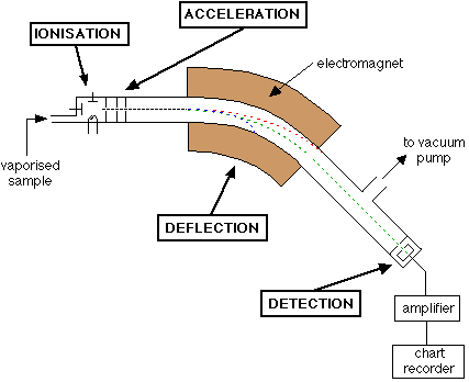
| You can apply exactly the same principle to atomic sized particles. An outline of what happens in a mass spectrometer Atoms can be deflected by magnetic fields - provided the atom is first turned into an ion. Electrically charged particles are affected by a magnetic field although electrically neutral ones aren't. The sequence is : Stage 1: Ionisation The atom is ionised by knocking one or more electrons off to give a positive ion. This is true even for things which you would normally expect to form negative ions (chlorine, for example) or never form ions at all (argon, for example). Mass spectrometers always work with positive ions. Stage 2: Acceleration The ions are accelerated so that they all have the same kinetic energy. Stage 3: Deflection The ions are then deflected by a magnetic field according to their masses. The lighter they are, the more they are deflected. The amount of deflection also depends on the number of positive charges on the ion - in other words, on how many electrons were knocked off in the first stage. The more the ion is charged, the more it gets deflected. Stage 4: Detection The beam of ions passing through the machine is detected electrically. A full diagram of a mass spectrometer
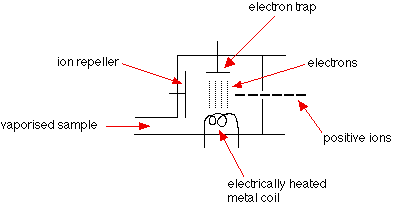
Understanding what's going on The need for a vacuum It's important that the ions produced in the ionisation chamber have a free run through the machine without hitting air molecules. Ionisation
The vaporised sample passes into the ionisation chamber. The electrically heated metal coil gives off electrons which are attracted to the electron trap which is a positively charged plate. The particles in the sample (atoms or molecules) are therefore bombarded with a stream of electrons, and some of the collisions are energetic enough to knock one or more electrons out of the sample particles to make positive ions. Most of the positive ions formed will carry a charge of +1 because it is much more difficult to remove further electrons from an already positive ion. These positive ions are persuaded out into the rest of the machine by the ion repeller which is another metal plate carrying a slight positive charge. | |
| Note: As you will see in a moment, the whole ionisation chamber is held at a positive voltage of about 10,000 volts. Where we are talking about the two plates having positive charges, these charges are in addition to that 10,000 volts. | |
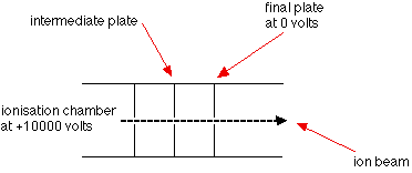
| Acceleration
The positive ions are repelled away from the very positive ionisation chamber and pass through three slits, the final one of which is at 0 volts. The middle slit carries some intermediate voltage. All the ions are accelerated into a finely focused beam. Deflection
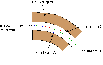
Different ions are deflected by the magnetic field by different amounts. The amount of deflection depends on:
These two factors are combined into the mass/charge ratio. Mass/charge ratio is given the symbol m/z (or sometimes m/e). For example, if an ion had a mass of 28 and a charge of 1+, its mass/charge ratio would be 28. An ion with a mass of 56 and a charge of 2+ would also have a mass/charge ratio of 28. In the last diagram, ion stream A is most deflected - it will contain ions with the smallest mass/charge ratio. Ion stream C is the least deflected - it contains ions with the greatest mass/charge ratio. It makes it simpler to talk about this if we assume that the charge on all the ions is 1+. Most of the ions passing through the mass spectrometer will have a charge of 1+, so that the mass/charge ratio will be the same as the mass of the ion. | |
| Note: You must be aware of the possibility of 2+ (etc) ions, but the vast majority of A'level questions will give you mass spectra which only involve 1+ ions. Unless there is some hint in the question, you can reasonably assume that the ions you are talking about will have a charge of 1+. | |
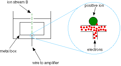
| Assuming 1+ ions, stream A has the lightest ions, stream B the next lightest and stream C the heaviest. Lighter ions are going to be more deflected than heavy ones. Detection Only ion stream B makes it right through the machine to the ion detector. The other ions collide with the walls where they will pick up electrons and be neutralised. Eventually, they get removed from the mass spectrometer by the vacuum pump.
When an ion hits the metal box, its charge is neutralised by an electron jumping from the metal on to the ion (right hand diagram). That leaves a space amongst the electrons in the metal, and the electrons in the wire shuffle along to fill it. A flow of electrons in the wire is detected as an electric current which can be amplified and recorded. The more ions arriving, the greater the current. Detecting the other ions How might the other ions be detected - those in streams A and C which have been lost in the machine? Remember that stream A was most deflected - it has the smallest value of m/z (the lightest ions if the charge is 1+). To bring them on to the detector, you would need to deflect them less - by using a smaller magnetic field (a smaller sideways force). To bring those with a larger m/z value (the heavier ions if the charge is +1) on to the detector you would have to deflect them more by using a larger magnetic field. If you vary the magnetic field, you can bring each ion stream in turn on to the detector to produce a current which is proportional to the number of ions arriving. The mass of each ion being detected is related to the size of the magnetic field used to bring it on to the detector. The machine can be calibrated to record current (which is a measure of the number of ions) against m/z directly. The mass is measured on the 12C scale. | |
| Note: The 12C scale is a scale on which the 12C isotope weighs exactly 12 units. | |
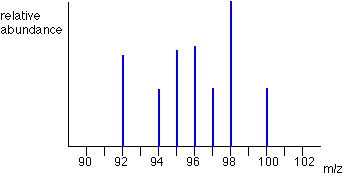
| What the mass spectrometer output looks like The output from the chart recorder is usually simplified into a "stick diagram". This shows the relative current produced by ions of varying mass/charge ratio. The stick diagram for molybdenum looks lilke this:
You may find diagrams in which the vertical axis is labelled as either "relative abundance" or "relative intensity". Whichever is used, it means the same thing. The vertical scale is related to the current received by the chart recorder - and so to the number of ions arriving at the detector: the greater the current, the more abundant the ion. As you will see from the diagram, the commonest ion has a mass/charge ratio of 98. Other ions have mass/charge ratios of 92, 94, 95, 96, 97 and 100. That means that molybdenum consists of 7 different isotopes. Assuming that the ions all have a charge of 1+, that means that the masses of the 7 isotopes on the carbon-12 scale are 92, 94, 95, 96, 97, 98 and 100. | |
| Note: If there were also 2+ ions present, you would know because every one of the lines in the stick diagram would have another line at exactly half its m/z value (because, for example, 98/2 = 49). Those lines would be much less tall than the 1+ ion lines because the chances of forming 2+ ions are much less than forming 1+ ions. If you want to go straight on to how you use these mass spectra to calculate relative atomic masses you can jump straight to that page by following this link rather than going via the menus below. | |
Subscribe to:
Comments (Atom)
BLOG SEKOLAH
BLOG PENTADBIR SMKSC
BLOG KETUA-KETUA BIDANG
BLOG PROJEK BUMI HIJAU
BLOG MAKMAL KOMPUTER SMKSC
BLOG PANITIA-PANITIA
LAIN-LAIN BLOG
About Me

- Habshah
- The world is still a very nice place to live even though we have millions of problems.